The Design Development Environments chapter in "Digital Design and Manufacturing" discussed common trends among CAD/CAM platforms in dealing with complex geometry. In thorough detail, it reinforced the necessity to plan ahead before you begin to model something. The end product should be considered in every modeling technique that you choose.
A couple of terms that were introduced to me in this reading that I had not yet heard before were "developable" surfaces and "nondevelopable" surfaces. A developable surface is a surface that can be converted into a planar form without cutting or stretching the original surface. On the other hand, a nondevelopable surface is a surface that does require cutting or stretching in order to be flattened. If you intend to eventually output actual cutsheets for a fabricator to cut a nondevelopable surface such as a dome, it might be a good idea to figure out ways in which the surface can be broken down into developable parts. This is just one example of why it is important to acknowledge the end product. I also found the example of the truncated cone piece for a tension-rod to be insightful toward this thought. The variables that could potentially change for the piece are the diameter of the rod and the thickness of the steel plate that it attaches to. With these in mind, the designer must make appropriate decisions about how to model the piece so that the variables are free to change. Extrusion operations might be off-limits, while lofting might prove to the best way to go.
I found the author's ability to refrain from being software-specific compelling. I tend to think that different software platforms perform in different ways. The reading, however, did an excellent job of remaining in a sort of common-ground. Reading about these techniques of modeling, editing, or subdividing showed me that these software developers have, to some degree, formed a set of general rules that work well for 3D modeling. No software has fully-exclusive operations.
Tuesday, January 28, 2014
Sunday, January 26, 2014
grossju - Project 001
The task of assignment 1 is to create a plan for a building, urban space, or object that I consider parametric in conception. I am fascinated by the complexity of Baroque architecture and see some of it as an early example of space that can be 'parametricized'. For that reason, I used Digital Project to model variations of St. Paul's Cathedral in London. Below is an image of its plan.
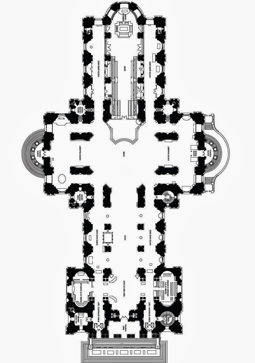


I re-created the plan in Digital Project by drawing a grid of column centerlines. In the original plan of the cathedral, I saw three basic bay widths. Every bay I modeled was given one of these three parameters. The centerlines were then offset on both sides with another variable to create wall thickness.
In the plan above, the large bays were doubled. This further accentuates the main corridor space of the cathedral and simultaneously downplays the small colonnades down the sides.
In the plan above, the medium-sized bays were doubled. This accentuates the colonnades down the sides as opposed to the inner-most bay.
In the plan above, the smallest bays were doubled. In this example, what was once a back-of-house space is now a grand space.
In the plan above, all bays were assigned the same width of 16'. This provides a sense of equality for all spaces, with the exception of the space at the intersection of the cross-plan where the columns have been removed.
In the plan above, I altered all of the variables, creating a drastically different plan from the original. The original plan is almost unrecognizable in this state.
In the above plan and detail, the wall offset distance was doubled, creating overwhelmingly large and imposing columns and structural walls.
The detail above illustrates the constraints placed upon some of the geometry that updates with the changing parameters.
All of the drawings were exported from Digital Project and annotated in Adobe Illustrator.
grossju - Project 001 Reading Response
"Keepers of the Geometry", by Yanni A. Loukissas presents assorted depictions of the role of software, specifically CATIA, in the architectural office. There are a few things within the article that I would particularly like to expand upon. The first was Loukissas's discussion on different perspectives of practitioners toward the software. In the example of Morris and Thorndike, the two designers look at and work on the same images on the screen, but are not "seeing the same thing." Thorndike, more atuned with the workings of the software, views his simulations as rays of light reflecting off of geometry and into a virtual camera. Morris views the same simulations on his own terms. He brings his experiences of drawing with pencil on paper into the simulation and sees lines, surfaces, and colors. The influence of different perspectives has always been desired within the architectural project team. In a time when working with software is unavoidable, this discussion shows that the same sort of collaboration does not end with the introduction of the computer, but can actually be enhanced.
The other bit I would like to expand upon is the consideration over a design's versatility once it is modeled on the computer. The belief of architect Rikle Shales, that "once they are represented, people tend to see the designs as frozen, as a done deal," is quite common within the architectural office. This thinking might have some historical accuracy, but in my opinion, some forms of parametric software have the potential to reverse this opinion. As attempted in this week's assignment on constraints and modifiable sketches, digital models that have been set-up correctly can be drastically altered by the simple change of one value or variable to another. Overall, I believe that much of the resistance of the incorporation of software like CATIA into the architectural office is due both a lack of understanding of the software, and an unwillingness to consider the software as a player in the control of the design.
The other bit I would like to expand upon is the consideration over a design's versatility once it is modeled on the computer. The belief of architect Rikle Shales, that "once they are represented, people tend to see the designs as frozen, as a done deal," is quite common within the architectural office. This thinking might have some historical accuracy, but in my opinion, some forms of parametric software have the potential to reverse this opinion. As attempted in this week's assignment on constraints and modifiable sketches, digital models that have been set-up correctly can be drastically altered by the simple change of one value or variable to another. Overall, I believe that much of the resistance of the incorporation of software like CATIA into the architectural office is due both a lack of understanding of the software, and an unwillingness to consider the software as a player in the control of the design.
Subscribe to:
Comments (Atom)